

The DAP4 was probably one of the most popular of the VDUs that were connected to the 8870/Quattro machine.
It had an inbuilt smudge grill guard on the front that can be be easily removed on the later version of the case; put your finger nails between the light grey and the dark grey frame and “peel” the plastic frame off. You can then wash the grill and either air dry or use an air dryer and clean the screen.
Typically the CRT in these VDUs is white with a thick orange/amber plastic layer over the top.
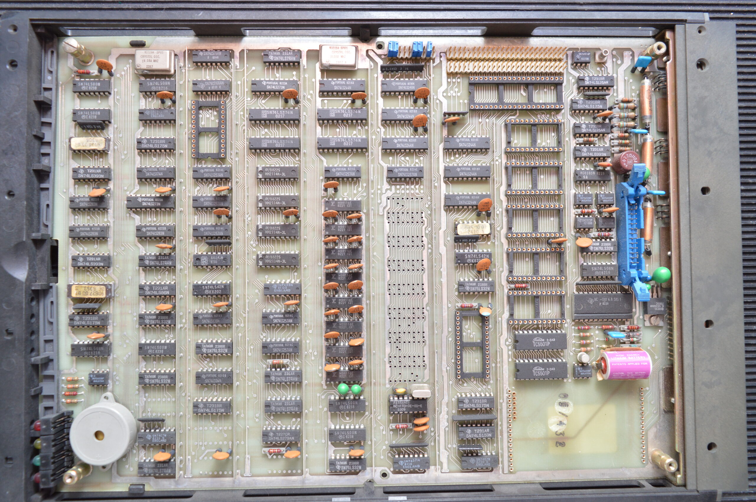
Removing the CPU board
In the bottom of the unit and access from the rear is the VDU CPU processor board. This board has a ribbon cable that connects it to the PSU that’s bolted on the back of the housing. There is also a fine video coax that connects the processor board to the back of the CRT.
To remove the CPU board there are two grey plastic catches, one each side of the board. Each has a screw that needs to be loosened and then the catch can be twisted out the way. If you’re lucky the internal catches are either loose or missing; you will soon find out.
Next there is a thick wire that connects to either of the two ground pins on the processor card located either side of the 25 way D-type connector. Just pull that towards you to release it.
If the internal catches are released then you can lift the board slightly and slowly pull it towards you. As the board comes forward you will see a ribbon cable that goes from the PSU to the processor board. There are two release catches (of they’ve not broken off) that you press down; one each side of the ribbon cable plug… you need to be firm. This will eject the header plug. Continue pulling the board slowly and on the right hand side will be a small video coax connector. Just pull this upwards firmly. You should now be able to remove the board completely.
If the board won’t lift up you will need to remove the lid and released the board catches manually.
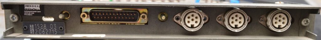
Connections
You can see on the back of the processor board there are three SAS connections and one 25way D-type connector. The 25Way connector is used to connect the VDU to the computer. The SAS connections are used to connect the keyboard and other peripherals. All the SAS connectors are the same so the keyboard and peripherals can be connected to any available socket.
Indicator LEDs
On the front edge of the processor card are four LEDs. These LEDs are visible though a small plastic window in the bottom right hand corner of the case below the screen. Three of the LEDs indicate the internal status of the VDU and the righthand red LED will flash when the VDU is communicating with the computer. Normally, the other three LEDs should always be lit.
Keyboard
Annoyingly the VDU has no visible self-test. This means when you power it on nothing will happen. When the VDU starts communicating with the host, the PSU will switch on the HT (High Tension Voltage) to the tube which you can usually hear as a soft static electricity sound.
If you press the keyboard keys the terminal will start beeping after two keypresses once the keyboard buffer is full if the VDU isn’t communicating with the host. Another reason for no host communication is if the VDU has lost it’s keyboard parameters. These parameters tell the VDU what protocol and communications speed to use and without them, you will never get the VDU working.
See DAP4 Keyboard Parameters for more information on this.
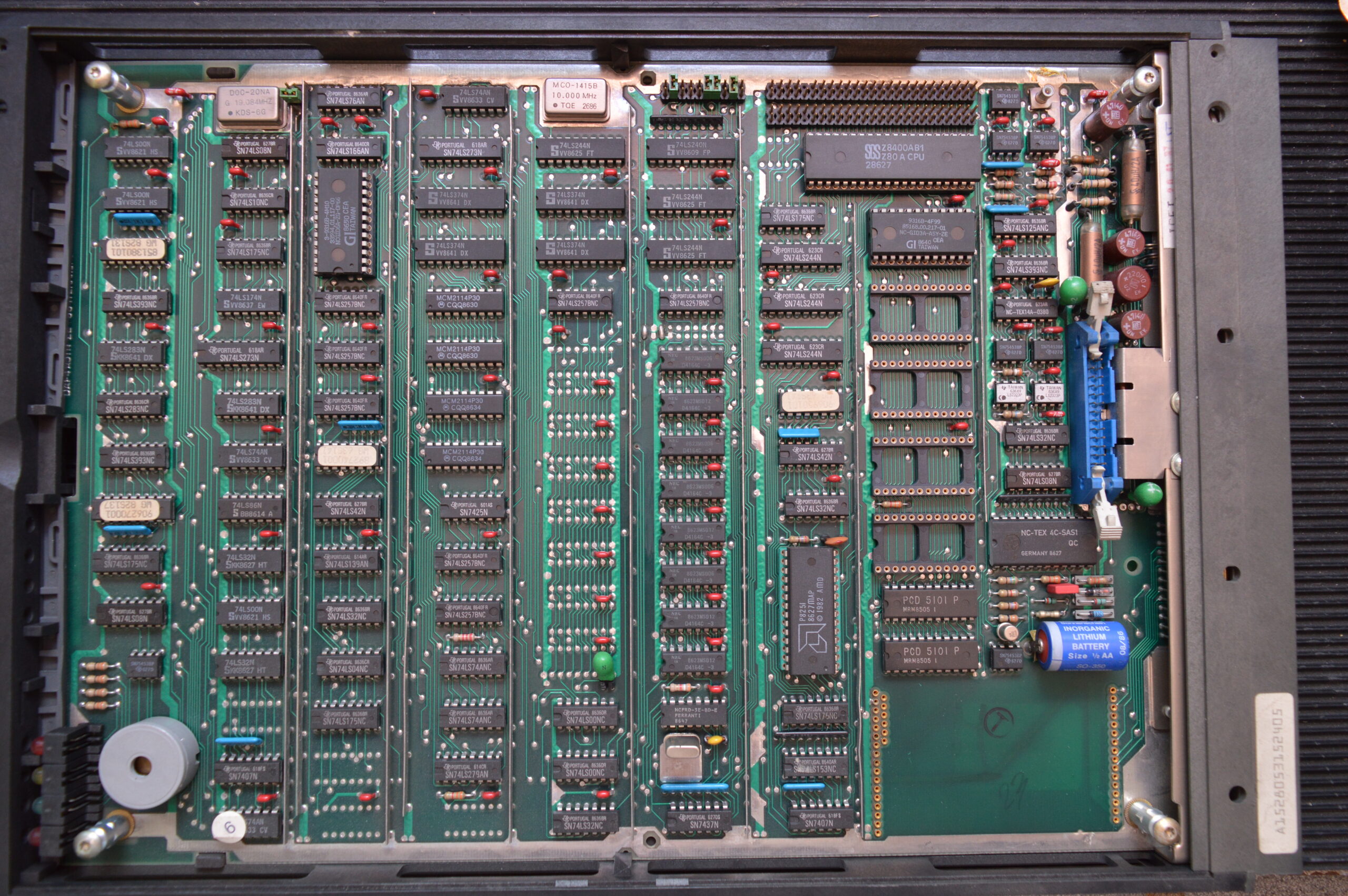
Personality cards
The personality card installed in the DAP4 must be of the same type as that installed in the ALME in the computer. If you have a master port (port #0 – of which there is only one per system), it will almost certainly have a V24 card with remote switch on capability installed. The ALME should also have a V24 card installed in ALME #0, Channel #0
All other channels; with the exception of ALME#0 Channel #1 which is reserved for the remote support modem, will usually have IHSS cards installed.
Irrespective of being connected with V24 or IHSS, no jumpers usually need to be changed on the VDU processor card itself. The communication speed is controlled by the user entered keyboard parameters.
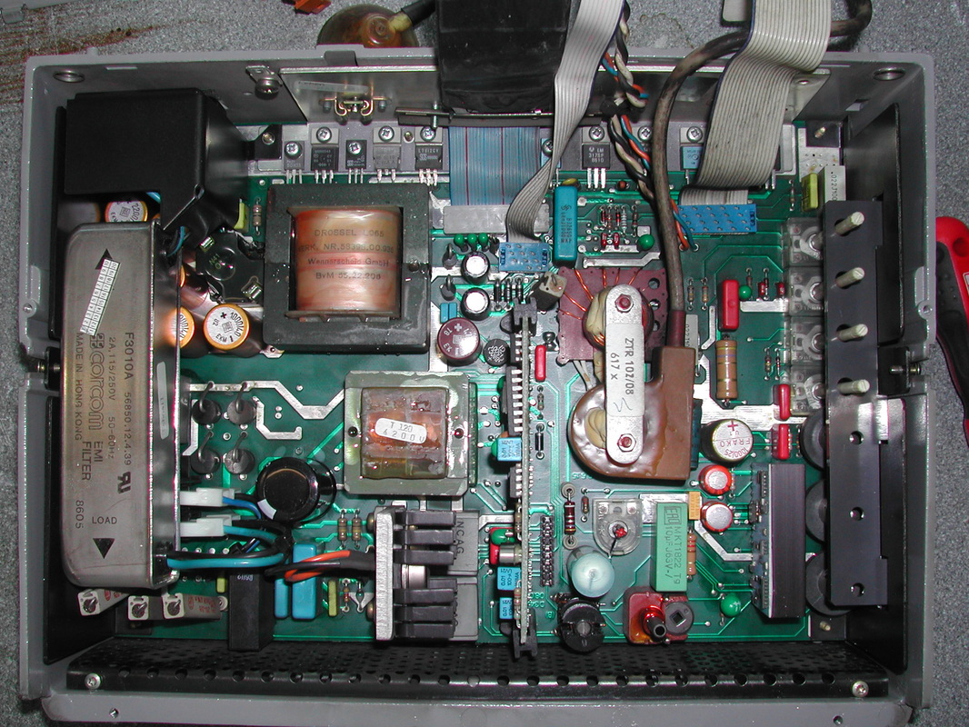
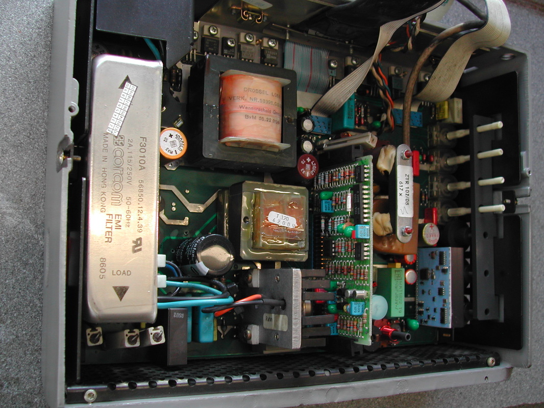
DAP4 SMPS (Switch Mode PSU)


1528-01

1528-03

1528-05

Leave a Reply
You must be logged in to post a comment.