

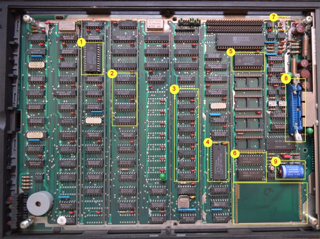
The above is a 1528-01 DAP4 VDU processor board with 16K of RAM. I’ve highlighted the main sections of interest.
I’ve currently no actual Nixdorf technical information relating to the 1528-0x DAP4 CPU, but what I’ve been able to figure out is here.
The DAP4 was in service for quite some time, and was used as the main workhorse on several Nixdorf machine ranges including the 8850, 8860 and 8870 systems. I suspect that the only real difference between these CPU boards would be the boot loader and jumper settings, but I’m not sure.
1528-01 16K program RAM
1528-03 32K program RAM
1528-05 64K program RAM
Note that any board not having the 7905 -5v regulator fitted (hole in PCB slightly above and to the right of the blue lithium battery), will not be able to use some of the older EPROMS that require a -5v supply rail to work.
I also can’t be positive that all of the above boards are suitable for use with an 8870. The 1528-05 should be (as long as it has the correct character generator, boot ROM and jumper settings as that’s the one I’m using.
Talking of the jumpers, I’ve four boards and they are all set identically except for the most left hand link. I suspect it has something to do with which bank of program RAM (left or right column) is installed. When it’s just the right column or both, then the link is missing. Just the left column installed then the link is present. It’s just a guess unfortunately.
Keyboard
There isn’t really much that can be said about the keyboards. They either work, or they don’t and I’ve never seen one that failed.
They are connected to the DAP via a short SAS cable. On some keyboards there is a connector at both end but on the newer (white) keyboards they are terminated at the keyboard end with a Molex connector.
All the keyboards I have are 0669-40 and are of the newer white colour.
Do take the base off any keyboards you get and remove any debris. You will find paper clips and all sorts of nasty rubbish in there.
1. Character generator ROM
On the early boards this used to hold an 2516 (2K x 8 bits) EPROM. Later versions of the board replaced this with a pre-programmed mask ROM. It contains the bit patterns required to form each character for display.
The 1528-03 board had an EPROM “33594 00 1 17 0001 ZG-DP66”
The 1528-05 board had a ROM “33594.01.117-00”
So it looks like the same ROM contents was used in these boards. However, watch out as EPROMS may not work correctly in the 1528-05 boards.
2. Video display memory
The CPU stores display data in four 2114 SRAM chips organised as 2048 words x 8 bits.
The screen has a maximum resolution of 80 characters x 26 lines (lines 0 to 24 are usable by the host, the last partial line is a system status line).
Since a screen of 80 x 26 would require 2080 bytes, 32 bytes more than available, only half of the last line is actually usable by the VDU CPU.
3. Main RAM
The memory in this section holds the workstation program that’s loaded from the host system. You can see there is room for 16 RAM chips (no parity on this RAM bank). I’ve seen total memory sizes ranging from 16K to 64K, though I’m not sure how much of that 64K is actually addressable.
4. Communications controller
Communications between the processor board and the outside world is handled via the P8251 UART. Check the datasheet for more information on this.
5. Boot loader ROM/EPROM
This is where the boot loader ROMs reside though I’ve never seen more than one ROM installed in this bank. In later revisions this contained a mask programmed ROM that replaced the earlier and much more expensive EPROMS.
The 1528-03 board had a boot loader “85168 00 2 17 0101 URLADER” This was an EPROM
The 1528-05 board had a ROM loader “85168.00.217-01”
So it looks like the loader program never really changed.
I’m guessing that this ROM is 8870/Quattro specific.
6. NVR – None Volatile RAM
The NVR consists of two, battery backed, PDC5501 or 5101 low power CMOS RAM chips organised as 256 words by 8 bits and this is where the keyboard/VDU parameters are stored so you don’t have to keep entering them every time you switch the terminal on.
The 5101 were used on the later release CPU boards, but the IC’s appear to be basically identical.
There is further information here about why the DAP4 processor board should be serviced IMMEDIATLY.
7. Video output connector
This socket accepts a fly lead that comes from a small PCB on the back of the tube and contains the composite video data for display.
8. Power supply connector
A ribbon cable from the PSU connects here and carries power and control signals back to the PSU
9. Lithium backup battery 3.5v
This battery is responsible for keeping power to the NVR when the terminal is switched off. Great in theory, and I suppose Nixdorf didn’t think these terminals would be around for 30 years, but the retched things have a habit of leaking and destroying the board. Look at it’s expiry date in the picture – 08/86. Amazing it’s not leaked.
10. Personality interface board
Located in the bottom right corner below the battery is space for the personality interface board and without something installed in here, the VDU will not be able to communicate with the outside world. Typically you have three options for the type of board to install.
The system master port (port #0) would typically have a V24 card with remote switch-on support. Turning on the VDU would also send a signal to the ALME which would in turn wake the make system. Turning off the VDU would no effect.
All other ports on a system would have a standard IHSS (in-house) board fitted. These allow fast data communication via simple 4 core cable over long distances (around 1KM).
A third option that is probably never used at a customers site is the V24 simple board. With this board installed, the VDU could be connected directly to a modem and was common for use in Nixdorf offices that offered customer remote support.
Other components
The boards contain other components that are worth mentioning.
There are several fusible link PROMs in use. The only technical data I’ve been able to find so far is this:
PROM: 63S141N
Fuse-Programmable PROM – Dual output enables
Number of Words=256
Bits Per Word=4
t(a) Max. (s) Access Time=45n
Output Config=3-State
Number of Chip Selects=0
Program Voltage (V)=12
Nom. Supp (V)=5.0
Package=DIP
Pins=16
Military=N
Technology=TTL
Another PROM that can be found is the HM3-7621A-5; again, a Fuse-Programmable link PROM.
I suspect that all the PROM variants are actually pin compatible.
Usually the PROMs are soldered in-place, but I’ve got one board where some of them are in sockets. It’s also a later variant board which implies that either the PROM was replaced as faulty, and/or as part of an upgrade.
Leave a Reply
You must be logged in to post a comment.