
The 8870/Quattro computer system houses a variety of boards or plates. They are have a uniform height and width and usually encased with a metal frame and aluminium side panels. One or more plates can be fixed together to make larger modules and one or more of the plates may have an LFI plaque affixed.
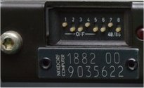
The LFI plaque contains the plate type (1882), variant (00) and a unique serial number.
There is often an additional round sticker located next to the LFI plate that shows the BZED (Revision) level of the board and it’s common to find plates have gone through revision work to correct minor bugs. It was also common to find that certain plates had to be of a minimum specific revision to support certain operating systems.
In a customer system each plate is pushed home firmly and then a screw from the rear tightened to hold the plate securely in place. However, it’s not common for plates to be screwed home with the exception of the PSUs, as it makes swapping faulty plates difficult.
Removing a plate is a dice with danger for your knuckles. The plate needs to be gripped at the top and bottom front edge and wiggled up and down whilst pulling towards you. You need to be carful as when the plate comes free it will shoot out and your knuckles with catch on the chassis. Nixdorf had a tool called the plate key that made removing plates a lot safer, but I managed for years without one… just be carful.
All PSR plates have their interface connections, configuration switches, indicator LEDs and displays along the front edge with the backplane connector running along the rear edge. Whilst some plates do have configuration switches and jumpers internally, the main enable/disable setting, and the plates memory address (if configurable) is set via an 8-way dip switch accessible from the front of the plate. Almost all plates (or at least one plate in a stack) have a configuration switch. Because Nixdorf liked reusability in everything they did, it’s common to see plates that have a cut-out for the configuration DIP switch but it’s just an empty hole (sometimes there’s a blanking plate fitted over the hole).
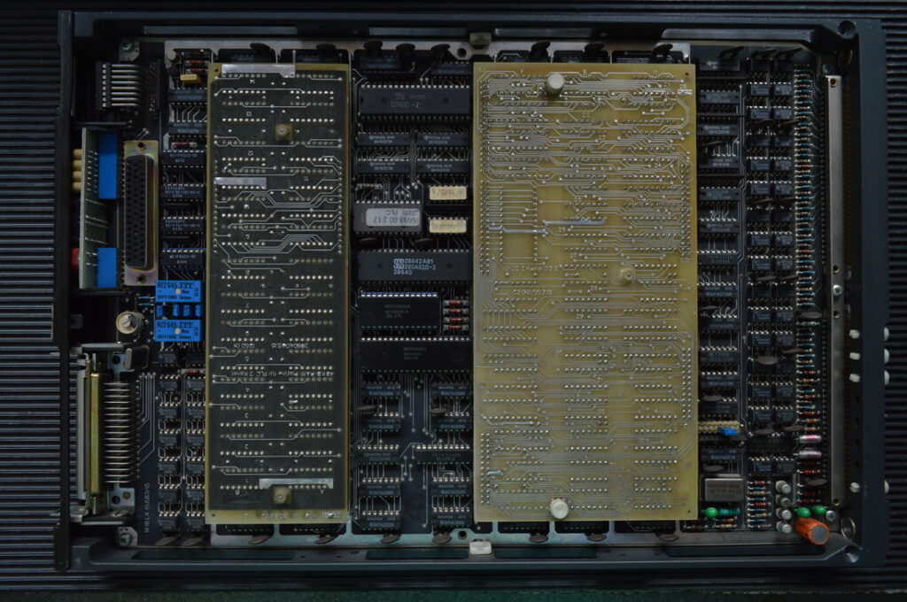
The above image is the internals of a PLC plate. You can see the configuration dip switch at the top left corner, there is there a display board that contains a couple of seven-segment displays and LEDs, then an interface connector at the bottom. On the right edge you can see the backplane interface connector. It’s common for Nixdorf plates to have one or more piggyback boards fitted.
Leave a Reply
You must be logged in to post a comment.