The PSR ALM(E); Asynchronous Line Multiplexer Extended, serves as the main interface between the computer and the outside world. ALM’s contain four identical data channels that can be configured in a number of different ways for different purposes. ALM channels are typically used to drive VDUs or modems, but can be used to connect to other serial devices like printers.
An ALME consists of a single plate and contains four communication channels, with each of the identical channels consisting of electronics, a small plugin interface personality board and an external 15pin male, D-Type connector. Each channel has an LED to indicate when the channel is in use.
There are two main types of ALME in general circulation; the 1882-00 and 1882-01 and for all intents and purposes they are the same with the main difference being the type of personality board that can be installed. Both variants have the same piggyback logic board – PSR EAGU ULA 34327-00-3-15 / 19-11-84/6(L)L4, though the 01 sometimes has 4 x TR1965-PL UART ICs but these are equivalent to the original AY-3-1015D ICs (Datasheet available).
Each ALME has an 8 way DIP switch that allows the configuration to be specified. DIP S/W 1 enables/disabled the board completely; this is common across many of plates in the 8870.

As can be seen from the above table, the system can in theory support up to eight ALMEs in a single system. The reality is that on a single CPU system you are unlikely to have sufficient core (memory) to configure a running system with more then 4 or 5 ALMEs and everything else that’s required. On a multi-processor system it’s a different story as ALMEs are configured for each CPU.
There was an older ALM; the 1819-00 which worked in a different way. This was a single plate again that plugged into the backplane, but the connections came out on the rear of the machine to a type of breakout box. The box had four 25 way D-Type connectors and also four SAS connections. These were PSP type ALMs and as far as I know were retired fairly early on. You are unlikely to see one these days.

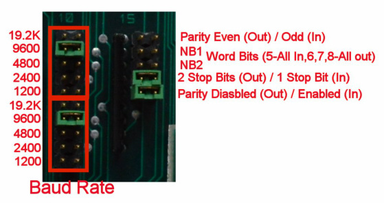
Each channel within the ALME as 15 associated jumpers. The reason there are two BAUD rate settings is to allow for different TX and RX speed on the channel. The actual communication is controlled via one of four AY-3-1015 UART ICs; one per channel.

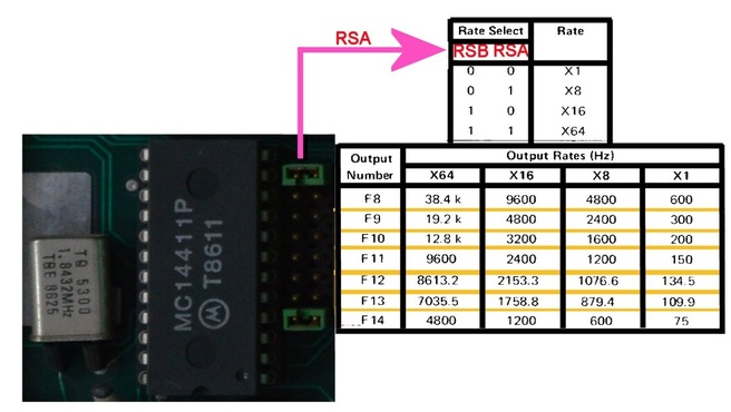
The ALME also contains a master clock generator that is used by the 4 x UART ICs.
The settings for this master clock are shown in the image on the left, but note that changing the master clock will affect ALL four channels on the board.
There’s a datasheet available for the MC14411 for anybody who’s interested.
Unfortunately, the RSB signal for the master clock is supplied by some of the ALME electronics and it’s not possible to see how this signal is manipulated.
Remote Maintenance Port
Every 8870 system I’ve seen has always has a remote support modem attached and it’s always been to channel 1 (second channel from the bottom on an ALME), and under NIROS 7.0 at least, channe1 is reserved for the this purpose. You cannot connect a VDU to this channel.
Remote Switch On
If configured correctly, the 8870 can be remotely switched on from port #0 – called the master port (bottom channel of the first AMLE).
However a personality card must be installed in both the ALME and the VDU that supports remote switch on and different VDU to computer wiring is required. Typically the master port would be located as close as possible to the main computer to enable simpler maintenance of the system. This is the port where the system backups and restores are performed so it makes sense to be as close to the computer as possible. The master port would also usually have a fast printer connected and this is where the system log is printed.
Remote switch on isn’t a necessity as the system can be started by either using the black or silver start key, or by triggering the PSU manually.
For information on the personality cards see this post.


Leave a Reply
You must be logged in to post a comment.